
ASPAR KNOWLEDGE BASE
Short answer
Do not construct a freight-lift shaft from approximate dimensions or a drawing from another project. First agree the load, platform, levels, loading directions and equipment configuration. The manufacturer can then issue design inputs, and the responsible designer can verify the building work.
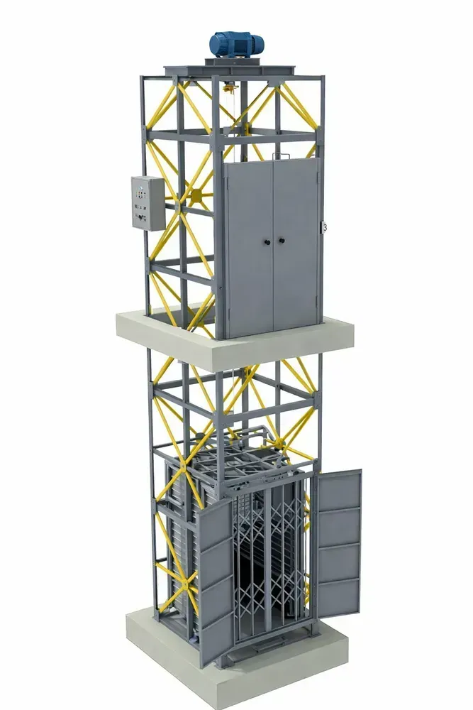
1. Do not begin with a “standard” internal dimension
The internal shaft size depends on the platform, guides, clearances, doors, guarding and installation zones. Clear platform dimensions are not the same as the structural opening.
Before construction begins, agree:
- load and container dimensions;
- clear platform dimensions;
- door positions;
- number of levels;
- actual finished-floor levels;
- shaft or frame type;
- installation and service zones.
2. Fix the opening coordinates
Door openings at different levels must match the approved loading arrangement. An error in entry side, threshold level or opening position may require the building work to be altered.
The setting-out drawing should use the same grids, levels and reference points for every project participant.
3. Check plumb and geometry
Measure the actual shaft over its full height, not only at the bottom. Projections, narrow points, beams, services or deviations may reduce the installation space.
Tolerances are defined by the project and the documentation for the approved configuration. A universal figure should not be applied to every system.
4. Coordinate the base and loads
The weight of the steelwork, platform and load, together with dynamic effects, is transferred to the building structure. The responsible designer determines the required base and reinforcement from the manufacturer's load data.
Do not install the equipment on a screed or an unverified slab. Equally, do not specify the same foundation for every lift.
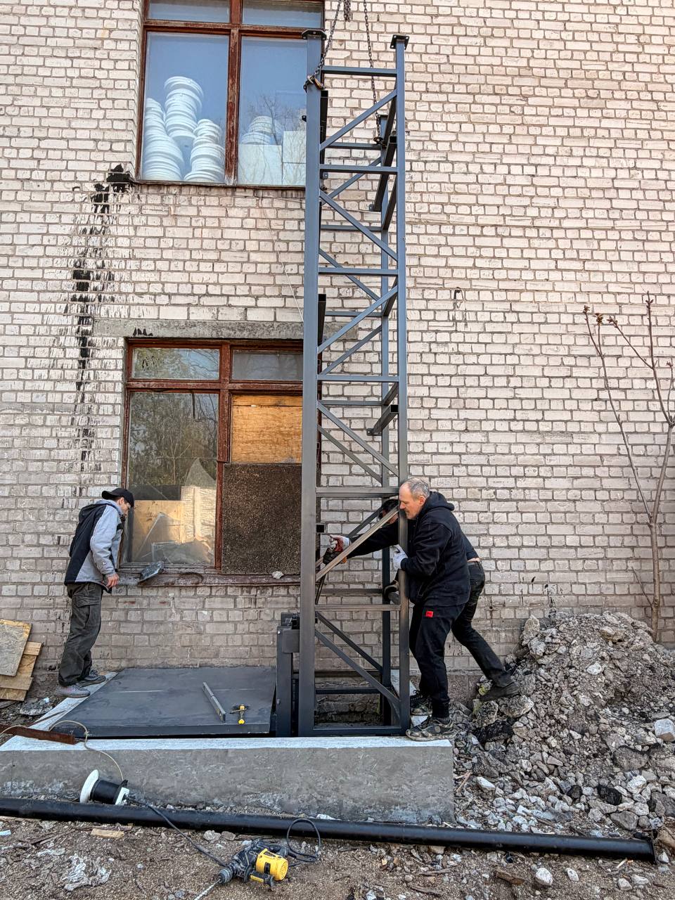
5. Pit and lower landing
The need for a pit, its depth, waterproofing, drainage and access depend on the configuration. If a pit cannot be provided, the manufacturer may assess a different arrangement, but it should not be promised before that assessment.
Define the finished-floor level in advance so that finishing work does not create an unwanted step in the loading area.
6. Building services
The shaft should not become a convenient route for unrelated pipes and cables. Coordinate services so that they do not obstruct the equipment, installation or maintenance.
Agree separately:
- power supply and connection point;
- protective devices;
- earthing;
- lighting for service zones;
- communication between levels, if required;
- moisture protection for an outdoor or unheated shaft.
Take specific electrical parameters only from the documentation for the approved model.
7. Installation access
Check how the steelwork and equipment will reach the shaft. Account for passageways, gates, floor openings, unloading space and safe working access.
If the building remains operational, agree the restricted work zones, programme and division of responsibilities.
8. Checklist before construction
- approved lift category and basic configuration;
- clear platform and loading arrangement;
- coordinated plan and section;
- levels for every stop;
- door-opening dimensions and positions;
- base and fixing loads;
- pit arrangement;
- power supply and earthing;
- no conflicting building services;
- delivery, installation and service access;
- allocation of building work between the parties.
Useful ASPAR pages
- Products: shaft freight lifts, ASPAR freight lifts
- Knowledge: how to choose a freight lift
- Solution: architects and designers
- Completed freight-lift project: 800 kg lift for a manufacturing facility in Kamianske
Next step
Send the plan and section, level data, loading arrangement and known structural constraints. ASPAR will check whether the information is complete before issuing coordination requirements.