Discuss your task: +38 066 307 58 87
When a load moves from a conveyor to a workstation or another process area, lifting height is only part of the task. The load support surface, direction of travel and equipment interfaces must also be agreed. A scissor lift table with rollers combines height adjustment with movement along a roller surface. These two operations need to be considered together to match the actual process.
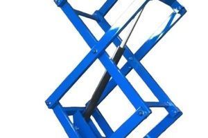
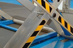
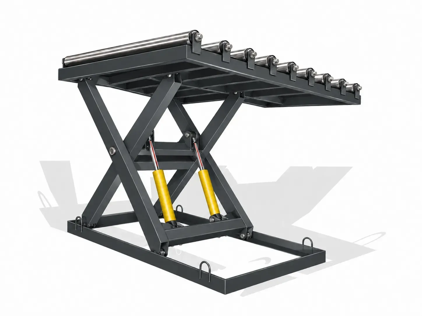
ASPAR designs and manufactures these tables with powered or freely rotating rollers. Capacity, platform dimensions, lower and upper working heights and integration functions are defined in the agreed technical specification. An illustration of the construction does not establish the specifications of a particular order.
Start with the load route
Describe one sequence: where the load arrives from, the height at which it is received, its direction of movement and where it leaves the table. Mark these points on a layout of the work area. If the table interfaces with a conveyor, provide information about the transfer point itself rather than only the overall height of the adjoining machine.
Photos of the area from several sides and a diagram showing the direction of travel help frame the discussion. Identify which operations an operator performs and which operations the equipment is expected to perform. This helps align the table functions with the actual operating cycle.
Check how the load is supported
The roller surface must suit the particular container, workpiece or packaged product. Selection requires the maximum combined weight of the load and its container, dimensions and photos of the underside support surface. Loads of equal weight should not be assumed to be interchangeable: their bases and feeding methods may differ.
If several types of load use the area, provide information about each one. State whether the load changes orientation during the transfer. Roller-surface compatibility is determined for the specific task.
Specify working heights at the roller surface
For the interface, specify the required lower and upper working heights at the roller surface. Include the location of the receiving and discharge areas and the direction of load movement. These details are needed alongside platform dimensions and information about adjoining equipment.
Do not substitute the height of the frame or an individual part in an illustration for the required working heights. The technical specification should clearly identify the surfaces between which the load is transferred and the positions in which the table operates.
Powered or freely rotating rollers
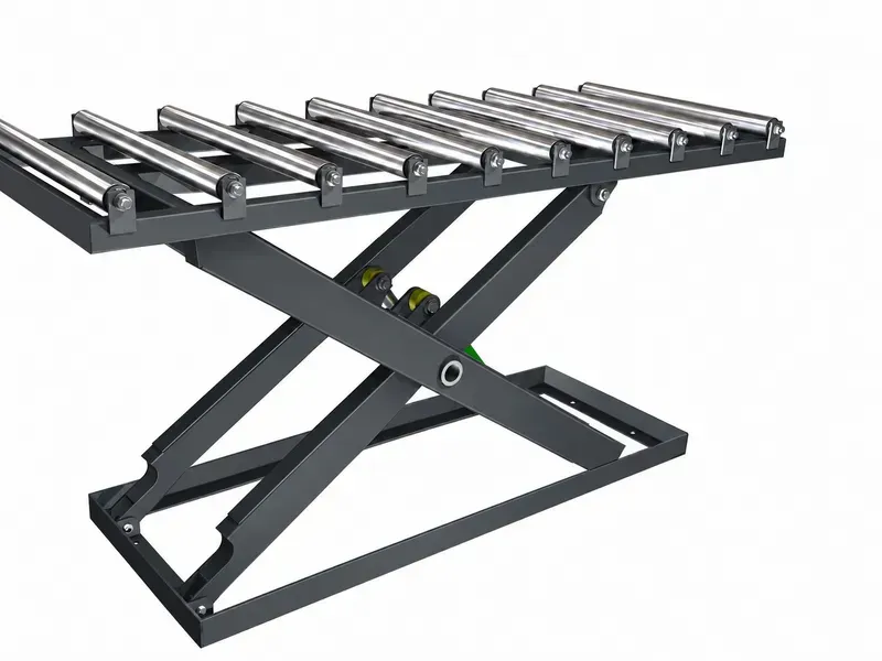
In a powered configuration, a drive moves the load using the rollers. In a non-powered configuration, the rollers rotate freely and the process determines how the load is fed onto and removed from the table. The choice should be tied to the route, load and required sequence of operations.
A scissor lift table with rollers can be integrated into an existing automated production line once the mechanical parameters, controls and safety requirements have been agreed. This includes the operating cycle, transfer sequence and interaction with adjoining equipment. A roller drive alone does not establish full automation or compatibility with every line.
Information to share with ASPAR
- A diagram of the load route and photos of the work area.
- The maximum combined weight of the load and its container, dimensions and photos of the base.
- The required lower and upper working heights at the rollers and platform dimensions.
- The load feeding and discharge directions and details of the adjoining conveyor or workstations.
- The sequence of operations, cycle frequency and operating conditions.
- The functions that need to interact with adjoining equipment controls.
If some information is not yet available, identify it as a question to resolve. Do not carry over the specifications of another table simply because the constructions look similar.
Frequently asked questions
Can any container be used on the roller surface?
Compatibility must be checked against the particular load support surface, weight, dimensions and handling method. Provide photos of the container base and information about every load variant.
Do powered rollers mean full automation?
No. The roller drive and the interaction between the table and the line are separate parts of the task. The operating sequence and control functions are agreed for the particular project.
Can capacity be determined from the illustration?
No. Capacity and other specifications for this table are defined in the agreed technical specification. The illustration does not establish the parameters of a particular configuration.
Explore the solutions
- Scissor lift table with rollers
- Scissor lift tables
- Manufacturing and workshop solutions
- Warehouse and logistics solutions
Start the discussion with a route diagram and load information. ASPAR develops the construction and configuration against an agreed technical specification.